Quote: "That looks perfect GG, nice work."
Thanks.

It's weird trying to develop a visual effect when you have no means of looking at it properly - I can only rely on the 3D maths involved.
Now that I've got the 3D effect with basic lighting and bumpmapping almost working it'll be worth putting together a demo which I hope to do sometime today.
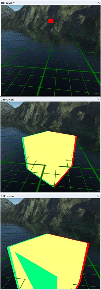
There is one small niggle which I haven't dealt with to my satisfaction yet. The following sequence of screenshots illustrates the problem using the basic 3D shader without lighting or bumpmapping:
Here's the shader code:
// Simple 3D shader
// Created 15 April 2009, edited 16 April 2009.

float4x4 wvp   : WorldViewProjection;
float4x4 wv    : WorldView;
float4x4 proj  : Projection;

float4 camOffset = {2.0, 0.0, 0.0, 0.0};

float4 leftColour = {0.0, 1.0, 1.0, 1.0};
float4 rightColour = {1.0, 0.0, 0.0, 1.0};

texture baseTexture < string ResourceName = ""; >;

sampler baseSample = sampler_state
{ texture = <baseTexture>;
  mipFilter = linear;
  magFilter = linear;
  minFilter = linear;
  addressU = wrap;
  addressV = wrap;
};

struct VSInput
{ float4 pos   : position;
  float2 UV    : texcoord0;
};

struct VSOutput
{ float4 pos   : position;
  float2 UV    : texcoord0;
};

struct PSInput
{ float2 UV : texcoord0;
};

struct PSOutput { float4 col : color; };

VSOutput leftVShader(VSInput In, VSOutput Out)
{ // convert to camera coords and shift to left
  float4 vPos = mul(In.pos, wv) - camOffset;
  // convert to screen coords
  Out.pos = mul(vPos, proj);
  Out.UV = In.UV;
  return Out;
}

VSOutput rightVShader(VSInput In, VSOutput Out)
{ // convert to camera coords and shift to right
  float4 vPos = mul(In.pos, wv) + camOffset;
  // convert to screen coords
  Out.pos = mul(vPos, proj);
  Out.UV = In.UV;
  return Out;
}

PSOutput leftPShader(PSInput In, PSOutput Out)
{ Out.col = tex2D(baseSample, In.UV) * leftColour;
  return Out;
}

PSOutput rightPShader(PSInput In, PSOutput Out)
{ Out.col = tex2D(baseSample, In.UV) * rightColour;
  return Out;
}

technique test
{ pass left
  { vertexShader = compile vs_2_0 leftVShader();
    pixelShader  = compile ps_2_0 leftPShader();
    depthBias = 0.0005;
  }

  pass right
  { vertexShader = compile vs_2_0 rightVShader();
    pixelShader  = compile ps_2_0 rightPShader();
    depthBias = 0;
    alphaBlendEnable = true;
    blendOp = add;
    srcBlend = one;
    destBlend = one;
  }
}
The rendering is done in two passes - once for the left hand cyan image, and then again for the right hand red image. The problem is that each pass puts Z depth information in the depth buffer - this is used to prevent the rendering of polygons (or is it pixels? not sure

) behind previously rendered polygons. In this case the left hand cyan surfaces of the cube are rendered first - and would (without the depth bias) be slightly closer to the camera than the corresponding left hand red surfaces from the second pass. Hence those red surfaces don't get rendered. The depth bias value used in the first pass of the shader is usually sufficient to fool the renderer into thinking that the cyan surfaces are always further away than the red surfaces. This allows the red surfaces to be rendered and blended with the cyan surfaces from the first pass.
So far so good - and that is what is happening in the middle image.
This technique seems to break down when the object is either a long way from the camera or, conversely, too close to it. There may be further related problems when other objects are placed in the scene - I don't know yet, but I expect there will be.
I'm not sure why it breaks down in the first image - I suspect that the bias is sufficient to put the cyan surfaces behind the background so they don't get rendered at all.
I believe the third image is caused by the limited precision available in the depth buffer (one of those irritating technicalities that is hard to track down precisely in the DX9 documentation) - so the bias is having no effect and the red surface is not rendered because the renderer still thinks it would be behind the cyan surfaces. I can minimize that effect by increasing the bias value - which of course makes the other problem worse (depth values are in the range 0 to 1).
Anyone have any ideas on how to solve both problems simultaneously?
The two camera solution is beginning to look far simpler - even though I don't find it aesthetically pleasing.