Low Poly Modelling Tutorial
Unfortunately, this tutorial is INCOMPLETE for the following reasons:
- I cant think of a way to logically explain (through a step-like process) how I model after the last written step on this tutorial. All I can say is its just a feeling you go with.
- The end resulting model isnt my greatest work at all, so I figure writing a tutorial on making a bad model isnt a very good idea.
- Ive got to get back to studying for my exams, after which time I may or may not be losing my computer for a while, limiting my time to work on this anymore.
Here's a screen shot of the finished product I was able to make;
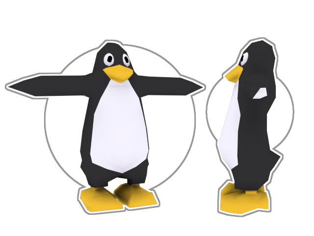
Im still posting this tutorial, because I think it still may help someone. Feel free to post any crit/comments in response.
On with the tutorial;
--
As indie developers, its important to use models that have the lowest polygon count possible, without sacrificing too much detail, in order to make sure your games run fast on everyone's compooters

.
Im not claiming im some uber master at low poly modelling, or modelling in general, but I think I've developed a bit of a style towards doing it, so I thought I'd share my basic technique.
This tutorial is pretty short, so instead of chapters its broken up into small steps, so it shouldn't be too hard. Lots of picees too

).

This tutorial is aimed at people using Wings 3D, a free modelling application that can be obtained from
www.wings3D.com. Some of the techniques involved in this tutorial might not be available in other modelling apps, but the theories and general guidelines behind them can still be applied.
Step 1: Decide on what you want to model (duh). For this tutorial, we'll be modelling none other than a PENGUIN! I figure, a penguin isnt so hard that there's tonnes of detail involved, yet its still simple enough to post more of a challenge than say, modelling a truck, which is mostly boxes extruded.
 Step 2:
 Find or draw some concept art. What I generally tend to do when it comes to getting concept art is first go to google images and search for pictures of what Im trying to model. The important thing is that you get a picture of the "subject" at as close to a straight-on view as you can. Even better is if you manage to get not only a front view, but a side view as well.
So, after doing a bit of searching, I found this;
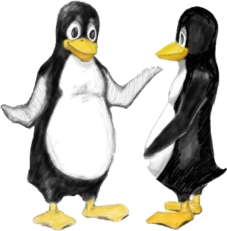
Its the linux penguin! Im not sure who drew it, but I found it off of linux's site. As you can see, we've got 2 views of the penguin, a front and a side. But theyre not very good, in both shots the penguin is at a bit of an angle. Which brings us to step 3.
Step 3: Nows the time for tracing. If you've got a 2D graphics program at home that allows the user of layers (like flash, adobe photoshop, or paint shop pro) then this will be much easier for you. Basically, we need to get an outline of the penguin. At the same time, we want to make the image of the penguin on the left a bit more "head on". One of my favourite tricks for getting a head on shot of something thats at a bit of an angle is pretty simple, you just take half of the shot, copy/paste it, flip it horizontally, and paste it over the other half. 9 times out of 10 this will get you the general shape to trace over.
So, after correcting the outline and tracing over, I've gotten this;
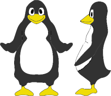
Which, isn't the greatest, Ill admit. But it works for what we need.
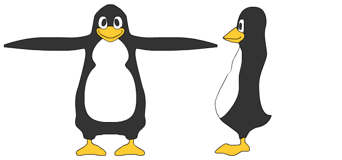
Step 4: Now, we need to put the penguin into the standard concept-art pose. Whenever doing concept art for organic beings, its usually a rule of thumb to have their arms pointing out, and their legs spread eagle with their feet facing forward. In the side view, its also common to remove the arms, since they're usually not needed in the side view.
Like so;
 Step 5:
 This is the last step involving concept art. What we're going to do is basically plan out the general area we want our verticies positioned on out model. To do that, we'll draw dots everywhere we think a verticy should go, following the outline of the concept art. This step isnt vital, but it does tend to help. However if you're not sure about where you draw the verts, you could enf up confusing yourself more than helping.
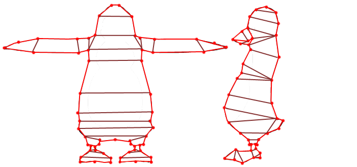
The wireframe doesnt have to be triangulated, you can use n-gons, whatever. Theres no rules, its your model, I just find that placing dots on the concept art helps me visualize where verticies should probably go during the modelling phase. Its not a rule, if you dont like how the model looks with a vert there, dont put it there, its entirely up to you.
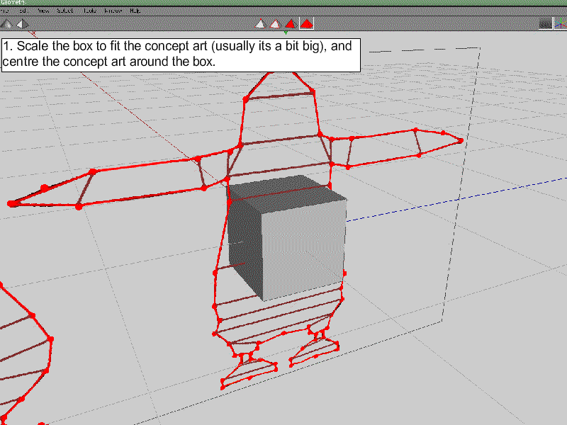
Step 6: Importing time. Open up Wings 3D, and right click. A menu appears, from the menu, select "Image Plane". In other modelling apps this may be import image. Basically this command will take an image, texture it onto a plain, and place it in the 3D world in Wings 3D. Its the same as texturing a plain yourself, just faster, so if you cant find a command to do this, go ahead and texture a plain with your image instead.

Once youve selected the image plain command, chose the concept art that has your wireframe drawn on it. If you didnt do a wireframe, chose the concept art that doesnt have a wireframe, its no big deal. The point here is, get atleast some sort of reference to your model into the 3D world to help you along.

After importing your image, create a cube (right click > cube). Time to "extrusion" model
.
Step 7: Now its time for the creative part. This process differs with everyone, so everyone will have their own style. Basically, extrusion modelling is done by constantly working in layers. You seled a face, extrude it, move the newly extruded verts around, then extrude the next face, and repeat. I cant quite explain this using words, so here's an animation demonstrating the first steps of extrusion modelling the penguin's torso;
As you can see, it might take a bit of learning, but its not all that hard. Its like those 3D puzzles that are made of layers.
Step 8: Well, we've got the front dont. Now we need to model the side. The first step is to make the penguin look less "blocky". To do this, we add edge loops! In Wings 3D, edge loops are a breeze. Whats an edge loop you ask? Well, atleast if my understanding is correct, an edge loop is when you cut all edges that are parallel on an object into 2, and then connect these edges to form, you guessed it, a new loop of connected edges. If that didnt make any sense at all, dont worry, just follow along.
So, first, select all of the sides (you can select sides in wings 3d by switching to side mode, which is the middle triangle at the top of the wings 3D screen) that are pointing in the same direction as the penguin. Like this;

And then perform a "cut" into 3 sections (right click > cut > 3). Now that you've performed a cut, select the newly made verticies (wings 3D will automatically select these verticies) and connect them (precc "c" in wings).
Now that the verts are connected, move them outwards (right click > move > normal) just a bit, to round out the model.
END (for now)
Sadly, I cant finish the tutorial for the reasons listed at the top of this post. Maybe at a later time, we'll see.
- RUC'