Sorry your browser is not supported!

You are using an outdated browser that does not support modern web technologies, in order to use this site please update to a new browser.

Browsers supported include Chrome, FireFox, Safari, Opera, Internet Explorer 10+ or Microsoft Edge.

3 Dimensional Chat / Cinema 4D Tips, Tricks and Tutorials 2!

Author
Message
BiggAdd
Retired Moderator
21
Years of Service
User Offline
Joined: 6th Aug 2004
Location: != null
Posted: 16th Jul 2006 20:42 Edited at: 16th Jul 2006 21:20
Hey There.... BiggAdd Here with another Tutorial for any C4D users browsing the Forums... or even any modeler (If they have similar tools).

Here is a link to my previous Tutorials :
http://forum.thegamecreators.com/?m=forum_view&t=68088&b=3


This time i will be making a Simple Low poly Chair. This is begginer level stuff so dont worry if your new. (I will do some advanced rendering techniques for all who know the modeling basics later)!

I will be splitting this tutorial up into two bits. The Bottom Half of the Chair fist... and then the top half later on.

There are lots of images to make it easier for you to understand!

Ok so here is what we are going to model for the bottom half of the chair:


1. Create a Cube Primitive by going into Objects=>Primitive=>Cube.
2. Change the Cubes Size as show below. The Y Height of the Box shall be changed to 20m


3. Make the Cube Editable By pressing C or by clicking this button that is found on the left hand side of the Cinema 4D Window:


4.Now select the Edge Tool by Going into Tools=>Edges or you can click this button found on left hand side of the Cinema 4D Window:


5. Now Select All the Large Edges on the cube. Do not select the smaller edges. This is show below. (The Smaller edges are the ones coloured Blue)


6. In the Above picture, it shows a little menu. This menu can be brought up by right clicking the mouse on in the window. Also see that the Bevel Tool is highlighted. Click on this tool and the following window will appear on the right hand side.

Notice above the inner offset box. Change it to 5m (unless it already is) and then click apply. Also see that the left hand side shows what will happen to your cube if things have gone to plan.

The edges look a bit soft.... we want them to be hard. In Cinema 4D, The Phong tag deals with your object's smoothing. The Picture below shows the object with and without a phong tag:


7. To get rid of this phong tag, Look in the object manager and delete a small igon next to the cube object that looks like 2 spheres:


8. Now that the Phong tag as been removed. The Seat Base has been completed. So we dont get it confused with other objects later on which will be created, we should rename it! Double click on the name "Cube" and type in the name "Seat" Or something else:


Now we shall make the legs!


9. Create another Cube Primitive, and change the dimensions to:
X = 20m
Y = 200m
Z = 20m
When this has been done, make the object Editable and going into Tools=>Polygons... Select the top polygon of the cube like so:

Now press Delete to remove the top polygon of the Leg. This is done because when the leg is positioned below the seat base, the top polyong will never be seen. therefore reducing the poly count.

10. Now change the view so the camera is looking into the Z Direction. This is done by going into View=>View4 or by pressing F4:


11. To position the leg, Type into the the coordiante manager the following values:
X = 85
Y = -110
Z = 85


As we cant have a chair with only one leg, we need to make 3 more copies of it.
To do this, go into Edit=>Copy and then Edit=>Paste:


Position the 3 legs with the values of:
X = -85 X = 85 X = -85
Y= -110 Y = -110 Y = -110
Z= 85 Z = -85 Z = -85

You should now have something that looks like this:


As we have now got 4 objects (All legs) it can get a bit messy. So what we can do, is we can connect those objects to create 1 object.

12. To do this, Select all the objects at once by dragging your mouse over them all in the object manager, or by selecting them individualy whilst holding shift. (Do no select the Seat object)


13. This is how you Connect Them. Once you have the object you want to connect selected... go into Objects=>Connect.

You will see once you have selected this button, that an extra object is created. This is the object you want and you can delete all the previous legs you made:


BiggAdd
Retired Moderator
21
Years of Service
User Offline
Joined: 6th Aug 2004
Location: != null
Posted: 16th Jul 2006 20:43 Edited at: 16th Jul 2006 22:01
Now to create the supports.

14. Make a new Cube Primitive, and set the demensions to
X = 150
Y = 20
Z = 10
Also Change the X Segments to 4.

Then when this has been done, make the object Editable.

15. Now in the polygon tool mode, select all the top faces of the support and then the two sides:

Press Delete to get something that looks like this:

The reason we delete this polygons is the same as before. When it is repositioned, they will not be visible. So by deleting them we can reduce the poly count.

16. Now position the Support with the following values
X = 0
Y = -20
Z = -85


17. Change your selection to Point mode after doing this, by going into Tools=>Points Or by clicking this button:


18. Also change the selection mode to a Live Selection. To do this go into Selection=>Live Selection or click on this button:


19. When you have clicked on the live selection button, The following window will appear in the bottom right of the C4D Program:

Make sure the "Only Select Visible Elements" Check box is not ticked. This will allow us to select polygons that aren't in veiw which is hand for what we will be doing in a moment.
(If this window doesn't appear, try clicking on the button again) (If that fails, go into Mode=>Tool)

20. Now go into View 4 (By pressing F4 or going into View=>View4)
and select the following points by clicking your mouse over them whilst holding down Shift.


21. Change the height of these points to Y = -15


22. Now select the outer points:


And change their height to Y = -30


This is now what you should have:


23. Make a Copy of this support and position it at
X = 0
Y = -20
Z = 85


The Next bit is a tad sneaky. It saves time making 2 more copies, rotating them and then positioning them.

24. Connect the 2 supports together to create one object:


25. Make a copy of this new object and rotate it 90 degrees:


And there you have it! you should have this:


I will do the top half of the chair a bit later, But hope you find this half of the tutorial easy to understand!

Comments and Feedback will be much appreciated.

Enjoy,
BiggAdd!

EddieB
21
Years of Service
User Offline
Joined: 29th Sep 2004
Location: United Kingdom
Posted: 16th Jul 2006 23:01
Very Simple but effective..

I wonder what that would look like under a hyper - nurbs object LOL!
BiggAdd
Retired Moderator
21
Years of Service
User Offline
Joined: 6th Aug 2004
Location: != null
Posted: 16th Jul 2006 23:24 Edited at: 16th Jul 2006 23:24
Very highpoly and probably looking very ugly
I designed the method of making this chair to basicaly cover a wide range of the things used in modeling.

EddieB
21
Years of Service
User Offline
Joined: 29th Sep 2004
Location: United Kingdom
Posted: 16th Jul 2006 23:36
Yeah, Good point ..

Get your self on MSN, I need some advice in c4d..
BiggAdd
Retired Moderator
21
Years of Service
User Offline
Joined: 6th Aug 2004
Location: != null
Posted: 17th Jul 2006 00:08
Ok. Will do. Was just writing some moooooosic.

Chris Franklin
20
Years of Service
User Offline
Joined: 2nd Aug 2005
Location: UK
Posted: 17th Jul 2006 00:11
Awesome thanks

Platformer Compo!
WHITEKNUCKLE IS BACK! Check the wip boards for more info
BiggAdd
Retired Moderator
21
Years of Service
User Offline
Joined: 6th Aug 2004
Location: != null
Posted: 17th Jul 2006 00:12
Cheers.

As i said its not complete yet. It takes ages to do this sort of thing. Will add some more 2morrow.

Seppuku Arts
Moderator
21
Years of Service
User Offline
Joined: 18th Aug 2004
Location: Cambridgeshire, England
Posted: 17th Jul 2006 01:21
Nice contribution, reminds me I haven't made one of my tutorials for a while, maybe I will over summer holidays if I decide not to enjoy the sun

BiggAdd
Retired Moderator
21
Years of Service
User Offline
Joined: 6th Aug 2004
Location: != null
Posted: 17th Jul 2006 17:08 Edited at: 17th Jul 2006 17:21
Ok Now to Add the Back of the Chair!

Here is a picture of what we are going to make:


25. Ok to get started we need to make a new Cube!
Here are the settings for the cube primitive:


26. Make the object editable and delete the bottom polygon from it. Now position the Cube
X = 90
Y = 160
Z = 0
You should now have this:


27. Now go into points mode and change the view to View 3.
Select this point shown (Make sure your in Live Selection mode and the "Only Select Visible elements box is unchecked):


And change its Z Value from -10 to -15
Then do the same for the point above it but change it from -10 to -20
Then the next point above from -10 to -30
The next one above that from -10 to -42.5
Then finaly the top point from -10 to -70.

When this has been done do the same for the opposite side but using positive vaules of Z.

This is what the result should look like:


28. Now Select the two polygons on the sides of the back plate as shown (Be carful about using Live selection here. You can select unwanted polygons. Your best option is to change the tool to the Move Tool. To do this go into Tools=>Move.):


29. Now go into Structure=>Extrude (Or right click the mouse and select it on the pop up menu)
In the right hand bottom corner of the C4D Program a new menu will pop up. Change the Offset value to 33 and press Enter or Apply:


Do this again but for an offset value of 30:


30. Now go into View=>View1. And also into Polygon Mode and select these two points:


31. Now go into Structure=>Weld. (Or again you can right click with the mouse and use the pop up menu).
Once you have selected these points, a yellow line will appear with a yellow box on it (If your using version 9.0 and above).
Make sure the yellow box is hovering over th point highlighted below:


Once clicked you should get this:


32. Repeat step 31 with the 3 other pairs of points.
You should now have this:


33. Go back into points mode and change the view to view3. Select these points (Making sure your using Live selection with the "Only select visible elements box unchecked):
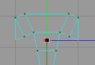

Change thier Y Value to 75.

34. After doing this, Select the bottom polygons of the "sticky out bits" you have just created:


35. Now go into the Extrude tool (Structure=>Extrude) and extrude for the following values:

46
60
60
61

You should have this:


Still with those poygons selected (You can see them red in the above picture) Press Delete, to remove them.

36. Go into Points mode. And select these two points:

Change thier Z Value to -74.
Now select the 2 points below them and change thier Z Value to -64
Select the points below these and change thier Z Value to -67.5
Finaly select the bottom points and change thier Z Value to -75

37. Repeat Step 36 for the other side, using positive values of Z.
This is what you should have:


38. Now go into View4. And using the same technique used in Step 36 change the back plate to this shape:


And your done! You should have this:


The Poly count on my model is 147. So fairly low poly for game use.

Again, any feedback and comments will be welcomed.
I hope this has helped you... i will be adding more tutorials in time. But for now..

Enjoy,

BiggAdd.

EddieB
21
Years of Service
User Offline
Joined: 29th Sep 2004
Location: United Kingdom
Posted: 17th Jul 2006 17:44
I thought it was a table , ( the top tut ) LOL!

What render is that? looks neat.
BiggAdd
Retired Moderator
21
Years of Service
User Offline
Joined: 6th Aug 2004
Location: != null
Posted: 17th Jul 2006 18:10 Edited at: 17th Jul 2006 18:11
Quote: "I thought it was a table , ( the top tut ) LOL!"

I did say i was making a Low Poly Chair.

Quote: "What render is that? looks neat. "


Just Standard GI. With a Cell Rendering Effect.

EddieB
21
Years of Service
User Offline
Joined: 29th Sep 2004
Location: United Kingdom
Posted: 17th Jul 2006 18:29
Ah cool

Yeah, I realised that LOL!
BiggAdd
Retired Moderator
21
Years of Service
User Offline
Joined: 6th Aug 2004
Location: != null
Posted: 18th Jul 2006 04:19 Edited at: 18th Jul 2006 04:48
Any other feedback?

The Next tutorial will either be:

Advanced rendering (HDRI and Global Illumination)
or
Mocca - Rigging Bones.

I just need to decide for that one. I may not start it untill Thurs. Im working on a model at the moment. But keep a lookout!

IceCube
21
Years of Service
User Offline
Joined: 3rd Apr 2005
Location: Munich, Germany
Posted: 18th Jul 2006 13:33
After a long time I was around here I thought of continue modelling again

@BigAdd: Could you please tell me how you do your render, because I can't figure out how to do it

BiggAdd
Retired Moderator
21
Years of Service
User Offline
Joined: 6th Aug 2004
Location: != null
Posted: 18th Jul 2006 15:23
Ok.

Go into Render Settigs. Then go to Effects.

In the Effects menu. on the very right hand side there is a tab saying "Post Effects", with a little arrow pointing right.
Click on the arrow and then select Cel Renderer.

When you have clicked this settings should appear

Select the boxes that say:

"Colour" "illumintaion" "Edges" and "Outline".

This will display the wireframe over your object.

When you have done this, whilst still in the render settings... Click on the Global Illumination tab and set it to standard.
Then Change the stochasttic samples to 32 instead of 300 (Makes the render quicker, but its less accurate)

Then whilst still in the render settings... click on the options tab, and then Uncheck the "Auto light" tab... it can ruin your render.
These are all the settings you need.

Now create a floor object and a sky object.... but dont add any lights. You should get the effect you want.

IceCube
21
Years of Service
User Offline
Joined: 3rd Apr 2005
Location: Munich, Germany
Posted: 18th Jul 2006 20:58
OK, thank you very much

Login to post a reply

Server time is: 2026-07-27 04:28:49
Your offset time is: 2026-07-27 04:28:49